Surgical Planning
On finishing diagnostic preparation the surgical plan can be compiled. It is supported by special panel which organizes the working steps into systematic (hierarchal) order:
- Type selection of head frame;
- Patient orientation selection (rotated stereotaxy in 90° increment relative to skull, head frame rotated positioning);
- Registration of stereotactic space to reference diagnostics by using marker intercepts (intercepts of lower and upper CT slices with marker lines; 2×12 intercepts);
- Selection of patient’s anatomic space (AC-PC-FALX) and transformation into the space of CT volumetric model;
- Path selection (Right-Left or in rotated mounting ANT-POST);
- Planning trajectory of DBS electrode, biopsy needle on diagnostic background;
- Archiving surgical plan with parameter setting of stereotactic frame.
Overview
CranioPass supports next interventions: deep brain stimulation (DBS) for Parkinson patient, stereotactic pallidotomy/thalamotomy and trajectory planning for brain biopsy with surgeries made by the next arc-based stereotactic frames: Riechert-Mundinger, MHT, MHT-INVERSE and MHT-RM-PASTER as well as Leksell and CRW. The planning of paths to target corresponds to the known stereotactic methods based on fixed frame; the goal is that, in the space of frame, the targets (tip of electrode or biopsy needle) and the parameters of polar coordinates to reach them could be calculated from position depicted from diagnostic images. The reference sequence can be resampled during preparation of frame-based stereotaxy. With the help of CranioPass, rotation is possible around all three (x-y-z) axes with maximum 20° and rotation center specified anywhere in diagnostic volume. Using this method the correct anatomic direction for image resampling can be easily set (like AC-PC plane). During the planning procedure the fusioned CT-MR diagnostic background is utilizable. The workflow is hierarchical, so called “top-down” steps are allowed, that means any change in a higher level (“top”) planning step clears all succeeding planning steps.
Selection of Head-Frame
Frame type selection is the first step in stereotactic planning (CranioPass Stereotaxy Planner: Head-Arc Selection (1)). Description of base type of different arc-based head frames is known from literature, first of all, the relationship between the marking procedure and the stereotactic space of frame. Several modifications of base types are known, for some of them is offered solutions by the program and in case of proper information further modifications can be easily fit into planning algorithms. Manageable frames by CranioPass:
- Riechert-Mundinger (RM);
- MHT, MHT-Vister, MHT-INVERSE, MHT-RM-PASTER;
- Leksell;
- CRW.
After locking selection, the program automatically sets the movable graphics for the marker system which is assigned to the actual frame. Further on, during registration this movable marker set should be aligned with visible intercepts in 2 slices for 3D representation.
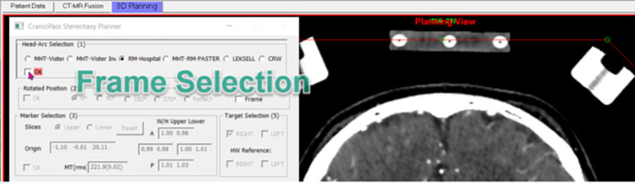
Image 11. Selection of type of stereotactic frame in control window. Marker plates not registered yet, the intercepts visible on CT slice and the movable marker graphics do not coincide.
Rotated Stereotaxy
The second step in planning gives a chance to fixing the head frame in rotated position to the skull (CranioPass Stereotaxy Planner: Rotated Position (2)). This setting can only be used for Riechert-Mundinger type frames. Different, rotated position – relative to the skull (0°,90°,180°,270° or Y-Z plane reflected) – frame gives support for those surgeries where the target area can be traced with otherwise hardly accessible 3D coordinates. According to the setting accepted by CT labs the patient is lying always on his back during scanning but the surgery can be done with rotated position of patient according to the fixation of frame. The marker system remains always in fixed position in scanner space. Stereotactic planning with CranioPass supports marker views and trajectory planning according to the surgical view. CranioPass permits planning appropriate to the rotated frame only in stereotactic planning view. In other orthographic view of the planning panel the program automatically compensates the rotated view and displays normal (lying on the back) surgical view. The archive file stores the rotation angle and reconstructs the rotated surgical view.
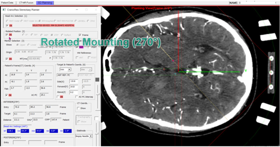
Image 12. Planning view during placement of frame rotated relative to the skull. The stereotactic space of frame is rotated 270° relative to the reference position, during surgery the patient is lying on his right side (the rotation is in clockwise).
The electrodes in this rotation setting can be anterior or posterior. The markers are fixed in reference position therefore the CT volume and the registration of markers similar to the reference setting, with identical rotation of the view and marker graphics. Display: fusioned CT-MR diagnostic.
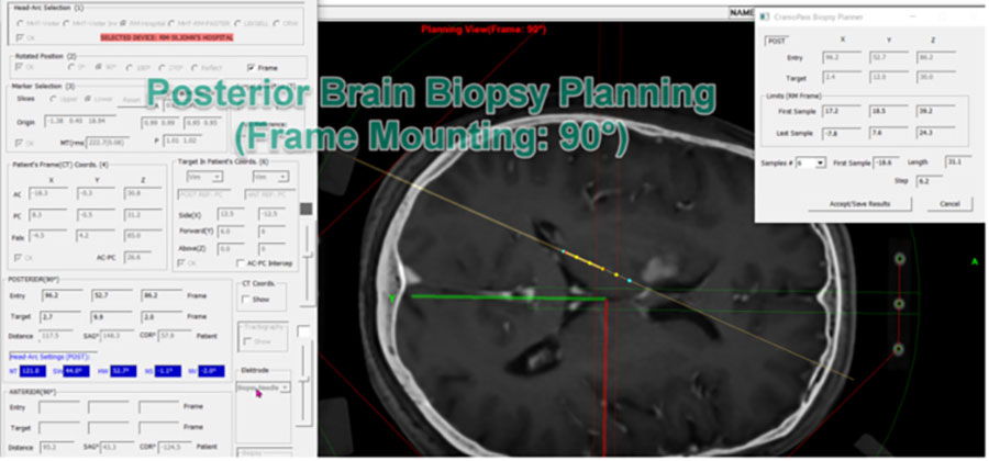
Image 13. Planning example for biopsy from posterior entry in right side of brain (mounting rotated stereotactic frame 90°). The patient is lying on his left side. Display: fusioned CT-MR diagnostic.
Registration of Stereotactic Space
After selecting frame type and rotation relative to the skull the registration of stereotactic space bounded to head frame can be performed (CranioPass Stereotactic Planner: Marker Selection (3)). This gives the way to assign any point from the reference space (diagnostic, usually CT sequence) to a point given in the stereotactic space. Each frame version has its own marker system which usually is implemented by metal wires fixed on marker plates. The CT scan is performed with attached marker plates always in the reference position that gives the possibility for using always the same marking procedure in case of rotated frame mounting.
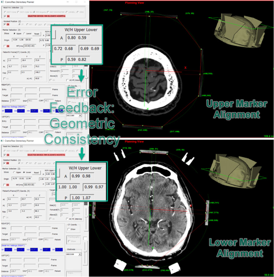
Image 14. Marker assignment for registration computations (above: upper slice, below: lower slice). The reference intercepts can be set in a lower and an upper slice with consecutive update of the transformation between the stereotactic space and the CT reference and real time refresh of actual error (W/H Upper Lower, MT (rms)). Change of any of 12+12 marker positions can modify the origo of stereotactic space in CT reference which can be tracked by the parameter “Origin”. The registration calculations can be reseted into initial state by command “Reset”. The error values of actual transformation are based on the estimation of geometric consistency of stereotactic space configured from the actual marker positions. Display: fusioned CT-MR diagnostics.
The intercepts with the upper and lower slices, according to the selection on control panel, designate the registration points. The CT coordinates of 12-12 such an intercept can be traced graphically by the user so that the program gives continuous feedback on the actual accuracy. Metrics of that: estimates of (1) so called W/H ratios for upper and lower intercepts that ideally approximates 1.0; (2) MT distance (distance of marker plates) ideally with 0 rms error value. The 3D registration algorithm in the same time with marker positioning continuously updates the optimized, orthogonal transformation between the CT reference points and the stereotactic positions and displays the actual error. The selection of upper and lower slices containing intercepts can be modified for better visibility. The registration algorithm is able to integrate the search for optimum of orthogonalized transformation with a feedback which gives continuous information on accuracy of marker localization. This way the program implements a convenient, interactive registration which is not supported by other stereotactic planning applications.
Registration of Patient’s Anatomical Space (AC-PC)
Known anatomical positions (AC, PC, FALX) determine patient’s own coordinate system (CranioPass Stereotaxy Planner: Patient’s Frame (CT) Coords. (4)). The registered projection between the stereotactic space and CT reference space calculated in previous step supports that, using anatomical markers of patient, the projection transforms, both between the patient’s space and CT reference and between the patient’s space and stereotactic space, can be determined. This way (using 3 anatomic markers) any point of the registered anatomic space in brain can be transformed into both references. Characteristic positions of the patient’s own anatomic space can be identified by anatomical atlas and, by this, the target points during DBS or biopsy surgeries can be refined. CranioPass uses its own database for selection of anatomic areas to initialize electrode target point. The coordinates calculated in patient’s space can be visualized in the stereotactic space of frame or in CT reference (“CT Coords.: Show”).
Display with Fusioned Diagnostic Volumes
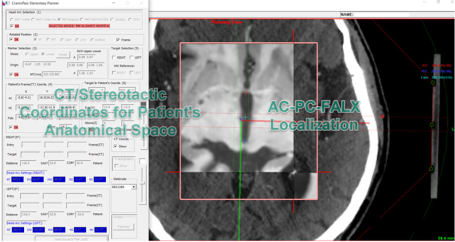
Image 15. Registration of patient’s own coordinate space by means of anatomical positions (AC: red, PC: blue, FALX: green). The 3 anatomic positions can be assigned in 3D space of CT-MR fusioned image view. The results of earlier registration (between CT reference and stereotactic space) can be used to calculate the transformed position of a point, depicted in the local anatomic space, in the CT reference or stereotactic space of head frame. Herewith, at the same time the anatomical target areas, given by the patient’s space coordinates, can be set more accurately.
Planning of DBS Trajectories (LEFT-RIGHT)
The planning of DBS electrode paths can be made interactively on CT-MR fusioned views using CranioPass planning panel (Target Selection (5), Target In Patient’s Coords(6)). During repositioning entry- and target points of electrode the whole graphical environment updated. The stereotaxic frame coordinates of a given point show up and CT reference coordinates with setup parameters of targeting arc are automatically modified (in case of Riechert-Mundinger frame these are: a distance NT and 4 angles; lateral SW, vertical HW and lateral NS, vertical NV inclinations). Two paths can be added: RIGHT-LEFT or in case of rotated frame mounting ANTERIOR-POSTERIOR (Target Selection (5)). In case of DBS stimulation important anatomic seeds as target areas can be selected in patient’s anatomic space. With selected areas the initial position of target can be defined (Target in Patient’s Coords (6): Vim, STN, GPi, Nacc and CM-Pf). With selecting entry or target positions of path the program sets the closest slice view. The selected point movable in X-Y plane with mouse while between slices can be stepped by mouse wheel. The intercept point between the path and the actual slice shows up in views. Reference position of diagnostic background, center slice position can be selected. The coordinates of end points of electrode path in stereotactic and CT spaces and orientation in patient’s anatomical space (AC-PC-FALX) can be updated in feedback mode with registration transforms calculated in previous steps. The electrode path can be adjusted numerically by overwriting local, anatomical coordinates of patient (Target in Patient’s Coords (6)).
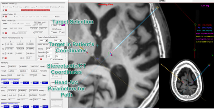
Image 16. Selection of the DBS electrode planning panel and the slice containing the LEFT target (CT-MR fusioned view). In right lower corner: selection of slice containing the entry position for LEFT path. Moving target point or entry position automatically updates parameter set of head-arc frame.
Selection of Electrode Model and Trajectory
CranioPass supports several electrode types and visualizes and inserts those models into the planning procedure.
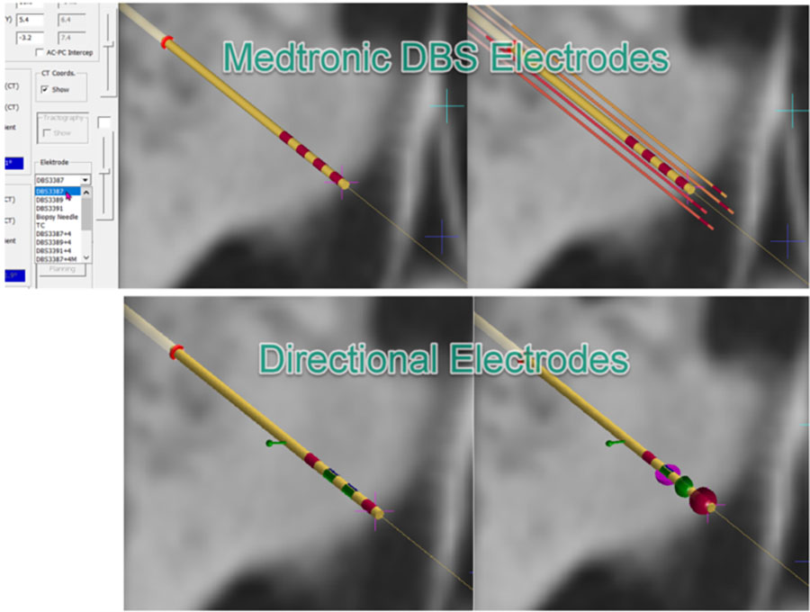
Image 17. Selection of Medtronic DBS electrode and directional electrodes in CranioPass planning panel. The program stores graphical models of several electrodes; beside “stimulating type” electrodes the modified (“stimulating-activity sensing”) types and directional electrodes with simple activity pattern simulations.
Compulsive DBS Trajectory Planning (HW-Controlled)
CranioPass is able to plan dual trajectories for Riechert-Mundinger type, arc-based stereotactic frame (RIGHT/LEFT) in compulsive (or controlled, HW vertical angle controlled) mode. To accomplish it, one of the paths should be assigned as reference (Target Selection (5): HW Reference: RIGHT or LEFT). Bilateral DBS implantation is frequent but extremely difficult surgical procedure that – if both trajectories are located on the same vertical arc – easier to perform. For this, CranioPass is supplied with a control algorithm which keeps both paths on the same arc (with constant HW reference) during planning. To meet this requirement, the program modifies in a feedback loop the entry point of the controlled path. The program monitors the changes in frame parameters and sends error message if any value crosses the acceptable limit. This function for checking parameter errors works in normal mode too and helps to finish planning quickly.
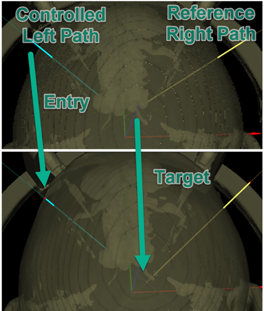
Image 18. DBS planning for Riechert-Mundinger type frame under HW vertical angle controlled mode. The entry point of the LEFT side path is controlled by HW value of the RIGHT side path. The program updates the parameters of the targeting arc frame under condition of keeping equal HW values for RIGHT and LEFT paths. Transparent surface view with trajectories.
Planning of Thermocoagulation (Directional TC Electrode)
Thermo lesion (thermocoagulation) is used for pain release during treatment of neuropathy. Planning option to this is implemented in CranioPass that is active after selecting “TC” electrode (“directional TC” electrode planning). The success of thermo lesion can be improved by extended tip of active electrode. The position, orientation of TC electrode path can be planned in correlation with an acceptable range of parameter setting of targeting head frame. In second step, the size and rotation angle of the active tip can be adjusted using some graphical extensions. This time the program supports the graphic model of TCU133 type which is used by the Neuro N50 lesion generator (Inomed Inc.). The target position can not be modified after the extended tip of electrode appears. The user can return to the regular mode of path planning (by double click of mouse on the target tip).
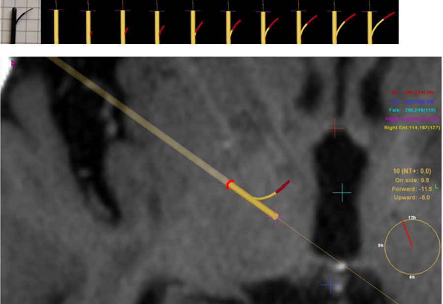
Image 19. The illustration of TC electrode model used by the planning software. The active end is displayed in red. The length of extended part of electrode can be changed in 10 equal stepsPlanning support for stereotaxy with TC electrode. After the trajectory plan is getting ready (similarly to DBS electrodes) the target tip of path can be extended by active TC protrusion using mouse double click on the target point. This extended ending of the electrode can be raised and rotated by mouse wheel about electrode axis. The target coordinates given in patient’s space (AC, PC, FALX) are displayed and the rotation angle is depicted on a supporting graphics.
Programming for Directional Stimulation (DBSJudeDir, DBSBostonDir)
Latest treatments with directional DBS brain electrodes offer high 3D flexibility for planning stimulation around electrode tip. CranioPass contains planning platform for elctrodes developed by Boston Scientific: https://www.bostonscientific.com/en-US/medical-specialties/neurological-surgery/deep-brain-stimulation-systems.html The systems are similar and during programming the current output from active surfaces is uniquely programmable and the intensity profile together with the active areas can be rotated about the axis of electrode. After selection of the type of directional electrode CranioPass brings forward a modelling window, where the active area can be selected and the charging intensity can be estimated by spherical surfaces
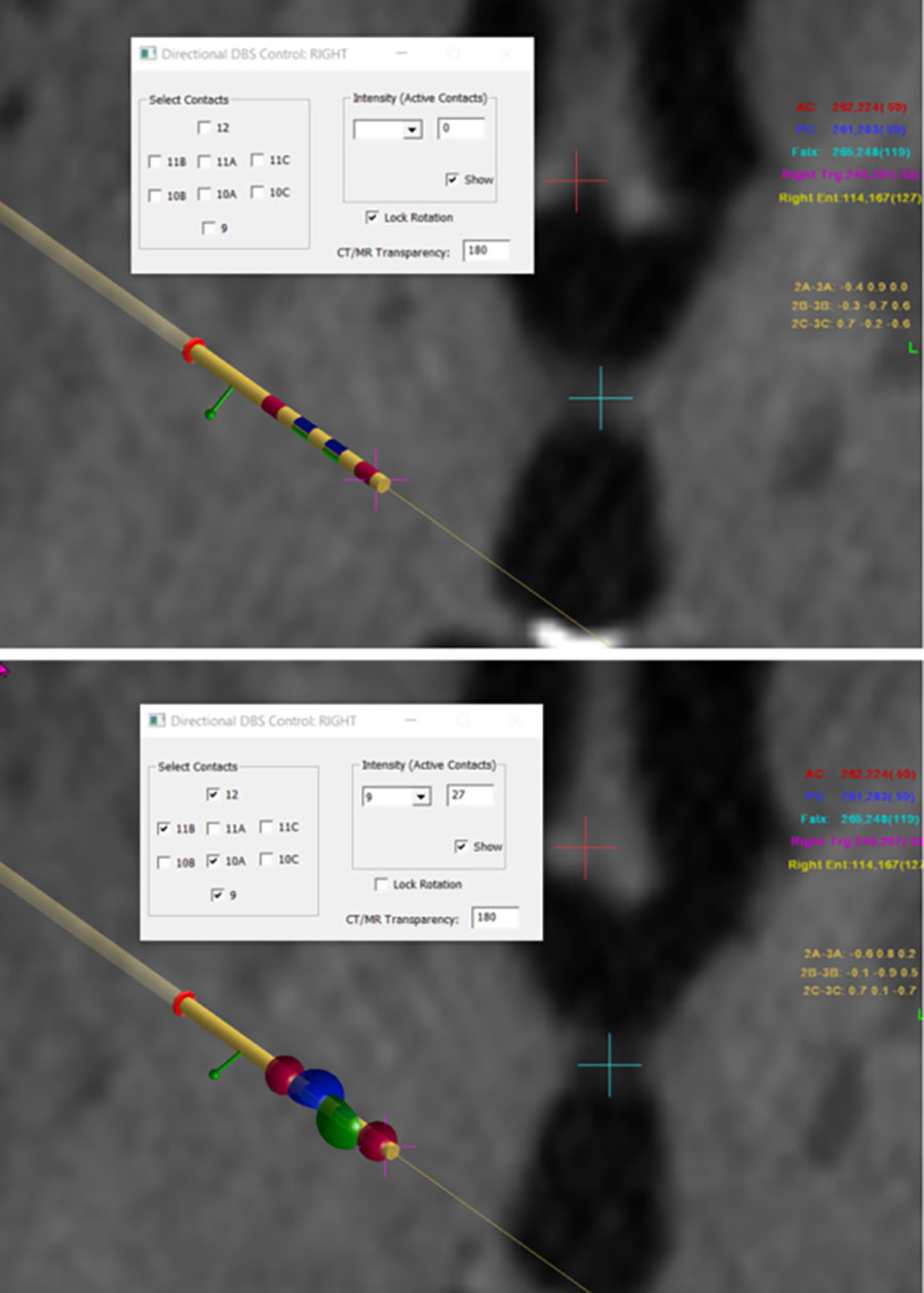
Image 20. Display of directional DBS electrode model in the planning software. Separate window will show up for selection of active areas and setting intensity values. The electrode can be rotated around its axis by mouse wheel. The slice steps (diagnostic background) can be changed from keyboard. Lower image: modelling directional DBS electrode in the planning program. In the overlap regions the intensity values are summed up
Biopsy Planning
Sampling positions in biopsy can be planned interactively by the help of “CranioPass Biopsy Planner”. In advance, similarly to the DBS planning, the trajectory (target point, entry point) can be set. After it, the sampling positions near target point along the path can be lined up with the mouse on CT or CT-MR fusioned background. The intercept between the path and the actual slice is displayed by the program. On “CranioPass Biopsy Planner” window the number of sampling positions can be defined and several other parameters are readable: 1/ coordinates of entry and target points in the frame coordinate space; 2/ coordinates of the first and last samples in the frame space; 3/ the distance of the first sample on the trajectory and the whole size of the sampling range.
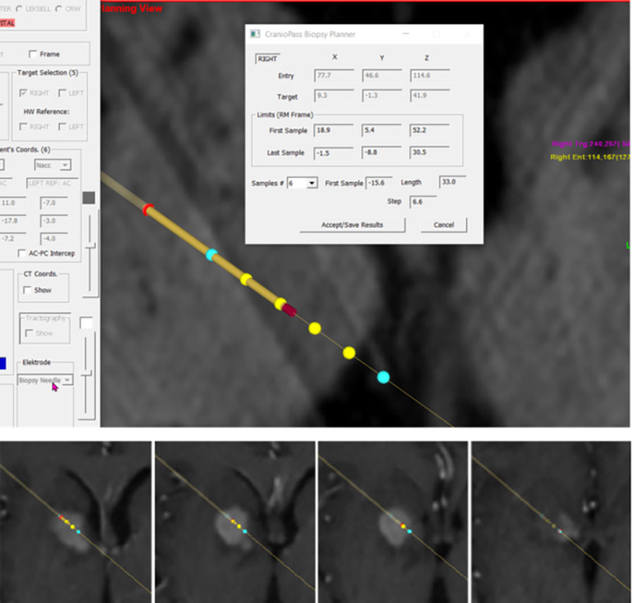
Image 21. Biopsy planning mode with the CranioPass Biopsy Planner window. After setting the path the sampling positions can be extended by the mouse. Lower row: archived sampling positions with the diagnostic background for post-operative control. The program archives the slices closest to the sampling positions in image sequence.
CranioPass CranioPassCranioPassCranioPass
CranioPassCranioPassCranioPassCranioPassCranioPassCranioPassCranioPassCranioPassCranioPassCranioPassCranioPassCranioPassCranioPassCranioPassCranioPassCranioPassCranioPassCranioPassCranioPassCranioPassCranioPassCranioPassCranioPassCranioPassCranioPassCranioPassCranioPassCranioPassCranioPassCranioPassCranioPassCranioPassCranioPassCranioPassCranioPassCranioPassCranioPassCranioPass